Auxiliary Payload Sensor Suite (APSS)


mission specific
Introduction
The Auxiliary Payload Sensor Suite (APSS) is a set of sensors consisting of the Pressure Sensor (PS), Temperature and Winds for InSight (TWINS), and the InSight Flux Gate magnetometer (IFG), all controlled by the Payload Auxiliary Electronics (PAE). These sensors provide environmental information that will be used in planning spacecraft operations (including instrument deployment) as well as to support SEIS (Seismic Experiment for Interior Structure) data analysis, and for their own scientific objectives. The figure below shows the locations of the components of the APSS equipment suite.

Location of each component in the APSS sensor suite.
Like the SEIS instrument, the APSS is designed to run continuously, and to record data without gaps at a high enough sampling rate to aid SEIS data analysis in search of seismic signals. In addition to being the first instance of a magnetometer at the surface of Mars, APSS will also be the first continuous and high frequency record of pressure, air temperature and winds at the surface of Mars.
Temperature and Winds for InSight (TWINS)
Introduction
TWINS is composed of two essentially identical sensor booms placed horizontally and diametrically opposite and parallel to one another on top of the lander deck, along the Y-axis as shown in the figure below. Each boom is a modified Mars Science Laboratory (MSL) Rover Environmental Monitoring Station (REMS) boom, and contains sensors for both 3-D wind and air temperature measurements. The deck placement is intended to minimize the effects of wind-flow perturbations induced by the other elements on the lander top deck by ensuring that at least one of the booms will be windward of the bulk of the lander body for nearly any given wind direction.

A view of the InSight lander deck, showing the location of the TWINS booms (circled in yellow).
Science Objectives
TWINS’ primary requirement is t o support SEIS by indicating when the winds are above 5m/s, representing a state when wind perturbations are likely significantly degrading the signal to noise ratio of the SEIS measurements. However, in addition to this crude indicator of SEIS data quality, TWINS will supply the time-resolved 3-D wind vector in the vicinity of the InSight lander, which can be used to estimate the detailed wind perturbations on the SEIS measurements. Additionally, TWINS will be used to characterize the local wind behavior at the landing site prior to and during the timeframe when the Instrument Deployment Arm (IDA) is moving the SEIS, WTS, and HP3 (Heat flow and Physical Properties Package) instruments to the surface to choose the best possible conditions and times, and to ensure the safety of that operation.
TWINS data will also be used for other science goals beyond those of SEIS. For example, TWINS data will be key in characterizing the local meteorology of the landing site, including diurnal tides, mesoscale circulations, seasonal variations, slope winds, and perhaps even transient waves. Dust devils are expected to be found at the InSight landing site, and TWINS data will be valuable in characterizing them. Because TWINS will be recording data continuously, it is uniquely valuable in quantifying wind thresholds for aeolian change and solar panel dust removal events. Additionally, simultaneous measurements from REMS at Gale Crater (data available through the Planetary Data System – atmospheric node) and TWINS at InSight’s landing site will help validate and improve meteorological models.
Instrumentation
Both booms are identical, and each carries a wind speed and direction sensor as well as an air temperature sensor. Wind speed and direction are provided by three sensor boards (2-dimensional hot film anemometers) arrayed around the tip of each boom. Each of these sensor boards consists of 4 hot dice and 1 cold die that sense the local wind speed and direction in the plane of the sensor. The three sensor boards are located 120o apart around the boom axis, as shown in the figure below. The full wind speed and direction is calculated by differencing measurements between the hot and cold dice, and then between the sensor boards facing in different directions. Readings from all the dice are sent back to Earth, where a retrieval algorithm is used to combine them with the pressure measurements, engineering data from the front-end electronics and the calibration curves to yield the wind speed and direction for each boom.

TWINS wind sensor detail.
The wind sensor has a response time of roughly 1s to wind perturbations, reducing its sensitivity to fluctuations above about 1Hz. The wind speed measurement has an accuracy such that wind speeds up to about 5.5 m/s will be sensed to within about 1.5 m/s. For wind speeds above this, the error bars increase, for example at 15 m/s the error bars are 2.85 m/s.
The air temperature is sensed using a small low thermal conductivity rod extending below the base of each boom (see the figure below). This rod has resistance temperature detectors (RTD) at its tip and midway along its length. Using these measured temperatures, as well as that at the base of the rod, the ambient air temperature can be estimated, despite the thermal contamination from the boom and the effects of solar radiation. The air temperature sensors response time depends on the atmospheric turbulence, being on the order of 30s in forced convection, although it will be sampled at 1Hz. It performs over the range of 167K to 277K with an accuracy of about 5K and a resolution of 0.1K.

TWINS air temperature sensor detail.
Instrument Operation
In general, only one TWINS boom will be operational at any one time for power considerations. However, to characterize the diurnal wind conditions and in preparation for placing SEIS, WTS and HP3 on the surface, TWINS may initially be operated using both booms simultaneously. Once the typical diurnal wind direction variations at the landing site are characterized, a boom-switching strategy will be employed to select the windward boom for operation at any particular local time. TWINS data will be recorded continuously, sampled at 1Hz. Under nominal downlink conditions, the full data set will be downlinked at a lower rate, namely 0.1Hz. For TWINS, the wind measurements will simply be sampled at the lower rate, as opposed to any more complex filtering as is done for SEIS and PS. For the air temperature measurements, they will be averaged to produce the downsampled values and a standard deviation over the averaging time will also be reported. As with the SEIS or PS data, selected “events” can be downlinked at the full data rate (within the limits of the downlink budget).
Calibration
The TWINS instrument has been calibrated using a low-pressure wind tunnel at the Centro de Astrobiologia (CAB). The wind sensor’s calibration curves were estimated for all the angular configurations and a significant number of Reynolds numbers within the expected operational range (pressure and speed). Using the same facility, dedicated calibration campaigns were performed to determine or refine the parameters involved in the end-to-end air temperature sensor numerical models. There are no means of re -calibrating the instrument after launch or on the surface of Mars.
Pressure Sensor (PS)
Introduction
The PS is a pressure transducer manufactured by TAVIS Corporation (see first figure below), located in the lander body, and connected to the ambient atmosphere with an inlet on the lander top deck (see second figure below). The inlet (see first figure below) is specifically designed to minimize the effects of wind on the pressure measurement, with a design similar to the “Quad-D isc” design developed for single inlet microbarometric measurements terrestrially (Nishiyama & Bedard, 1991). Before deployment, the WTS (Wind & Thermal Shield) will cover the Quad-Disc inlet for the PS (see third figure below). The Pressure Sensor’s sensitivity to winds may be increased (likely <1Pa for 7m/s winds) until WTS is deployed, but the pressure measurements will likely still be meteorologically useful during this pre-deployment timeframe.
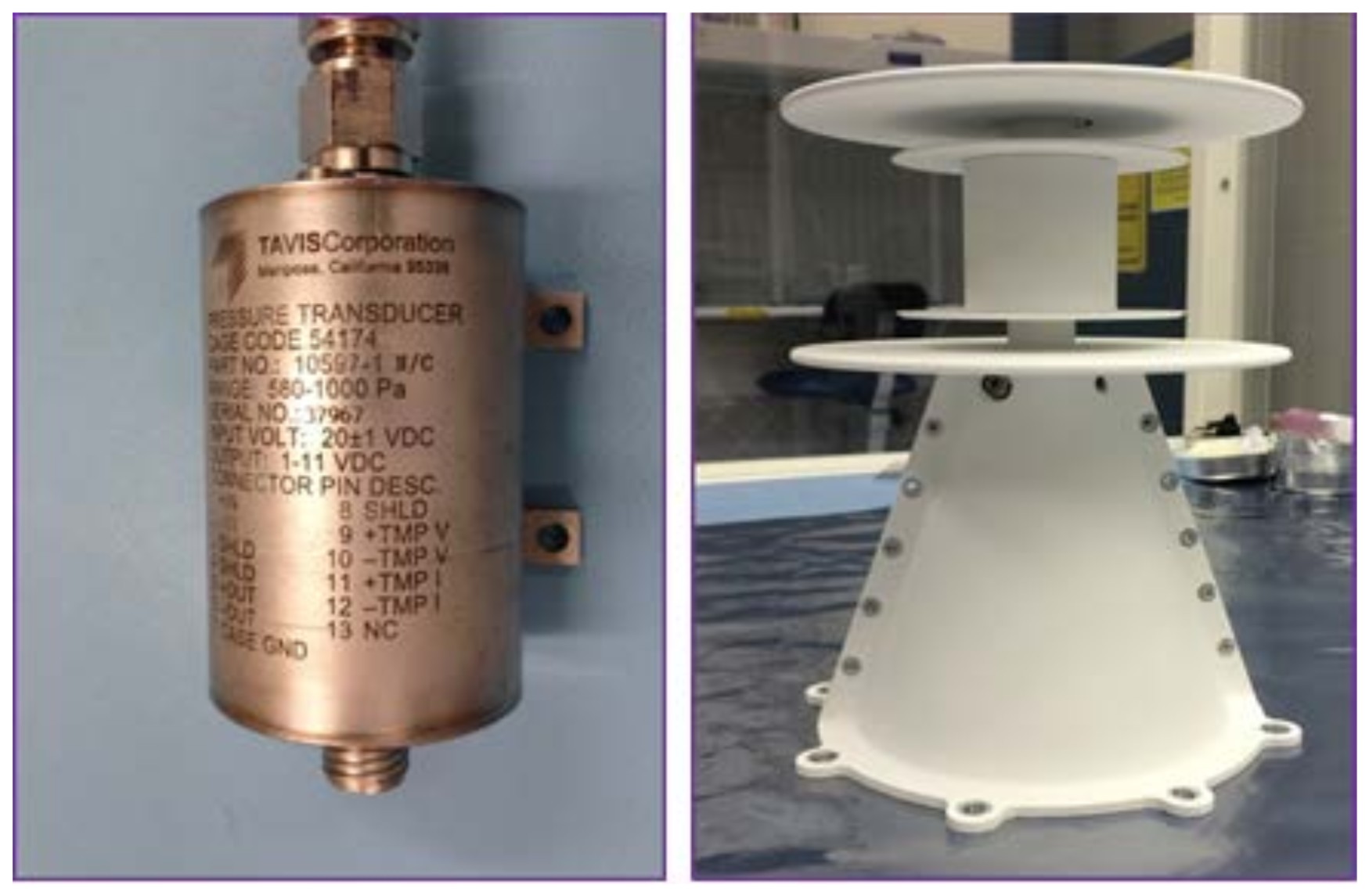
a) The Tavis Pressure Sensor and b ) The Quad-Disc pressure sensor inlet.
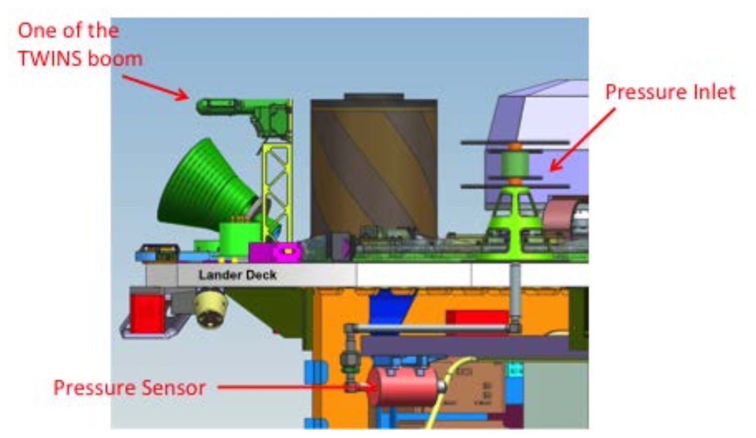
Location of PS and TWINS on the lander deck.
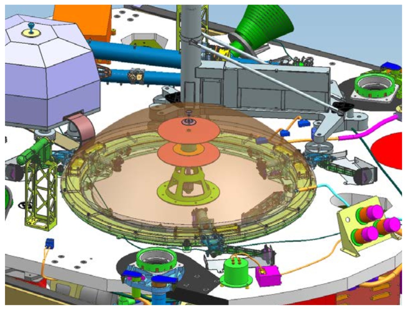
Showing the pre-deployment configuration with the WTS covering the pressure-inlet sensor.
Quad-Disc inlets under terrestrial conditions reduce wind effects (dynamic pressure) on pressure measurements to 1% to 0.01%, depending on the Reynolds number of the flow (worse at high Reynolds number). On Mars, the Reynolds number will be about 2 orders of magnitude smaller than on Earth, so the Quad-disc should reduce wind dynamic pressure effects to on the of order 0.0001% (i.e., <1mPa for 1000 Pa ambient pressure). However experimental studies have not been able to empirically confirm this level of performance due to the very difficult nature of such a measurement.
Science Objectives
The pressure sensor’s main purpose on InSight is to supply high-frequency, high-precision pressure measurements for use in decorrelating atmospheric pressure-induced noise from the SEIS measurements. It will also be used to pursue atmospheric science objectives. For example, as the fastest-response, highest-sensitivity continuously sampling pressure sensor ever sent to the surface of Mars, it is expected to contribute in dust devil, bolide, gravity wave and infrasound searches, and perhaps in other ways not anticipated.
Instrumentation
The sensor itself is designed to produce valid output between pressures of about 560 Pa and 1000 Pa, which are expected to be the extreme pressures that will be experienced at the InSight landing site (based on VL1 and MSL data and MOLA altitudes of the landing ellipse). The actual calibration is temperature dependent so the ultimate range possible for the instrument will depend on the thermal environment experienced. The sensor is specifically designed to minimize noise, with a typical RMS of about 10 mPa on any particular reading. The instrument’s noise spectrum meets the design requirement of:
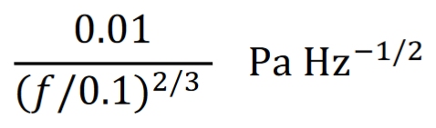
for 0.01 < f < 0.1 Hz and 0.01 Pa Hz-1 /2 for 0.1 < f < 1 Hz.
Placing the transducer within the body of the lander allows it to remain in a relatively controlled thermal environment, minimizing temperature effects corrupting the pressure measurement. Nevertheless, the pressure sensor also includes a temperature sensor near the sensor’s active element. This is required for accurate calibration of the sensor voltage readings to actual ambient environmental pressures.
The inlet tubing between the atmosphere and the pressure sensor itself produces a response time (or alternatively a cutoff frequency) for the instrument. For perturbations shorter than this time, the sensor’s response will be reduced. The cutoff frequency due to the inlet plumbing of the pressure sensor is roughly 6 Hz. There is also a first-order electrical low pass filter on the sensor output with a cutoff frequency of about 3 Hz. The sensor is read by an Analog to Digital Converter on the PAE at 500 Hz, which is then averaged down to a 20 Hz data stream. The two cutoff frequencies in the system provide adequate anti-aliasing filtering for the 10 Hz Nyquist frequency of the fundamental data rate of the pressure sensor.
Instrument Operation
The pressure sensor is designed to operate constantly throughout the mission, only being turned off in case of low power availability. Because the pressure decorrelation is crucial to interpreting the seismic signals, pressure data is needed at all times of the mission. The native sampling rate on board the lander is 20 Hz, although downlink budgets preclude returning all of this data to Earth. Instead, on-board processing will filter and downsample this to a lower sampling rate continuous data stream, as well as other processed versions of the full signal to indicate energy in the pressure signal at frequencies above the continuously downlinked sampling rate. For the nominal downlink case (~38 Mbits/Sol), the pressure sensor will return continuous data downsampled to 2Hz, and its temperature sensor will be downsampled to 0.2 Hz. Onboard processing will also produce the RMS of a high-pass version of the pressure signal above 1 Hz, which will be downsampled to 0.5Hz. This latter signal is expected to be indicative of high frequency pressure variations above that resolved in the continuous pressure data, to focus attention for downlink of the full sampling rate data in an "event". There will be a certain amount of the downlink budget allocated to "events" which will be special times in the mission where anomalous signals are detected in the pressure (or seismic or wind or magnetic) data sets, and full temporal resolution data sets are desired. In this case, the full 20 Hz data set from the pressure sensor (or a downsampled version of it) can be downlinked for a short period (~30 minutes/sol).
In the case of extremely small available downlink, the so-called Direct-To-Earth (DTE) case, only about 0.9Mbit/Sol is expected to be available. In this case, the continuous data will be much more severely downsampled (down to 0.1Hz for Pressure and 0.01Hz for the temperature of the pressure sensor). An on board computation will be performed of the average of the RMS of a high- pass version of the pressure signal (above 1 Hz), as well as the maximum of that RMS, both downsampled to 0.001 Hz. Finally, to aid in detecting events like dust devils, an additional on board computation will be done of the average and maximum of the RMS of a bandpass version of the pressure signal (between 0.025 Hz and 1 Hz), downsampled to 0.001 Hz. All of these computed signals will be in the continuous data stream, to aid in selecting events in this low data volume case.
Calibration
There are no means of calibrating the PS after launch or at the surface of Mars. Because the sensor does not respond below pressures of about 560 Pa, the vacuum of deep space during cruise will not be useful for calibration. The pressure sensor was calibrated using a Mars atmosphere simulation test chamber at JPL. This chamber was capable of modulating the pressure in the chamber up to frequencies approaching 1Hz. The PS transfer function was flat up to 1Hz, but theoretical predictions will have to be used to estimate the transfer function between 1Hz and the Nyquist frequency of 10Hz.
InSight Fluxgate Magnetometer (IFG)
Introduction
The IFG is a three-axis fluxgate magnetometer manufactured by UCLA, located beneath the lander platform on the main lander body (see the first figure in this topic). It will measure the magnetic field vector in addition to the temperature of the sensor. The magnetic field measured by IFG consists of contributions from naturally occurring sources (Mars’ fields) and magnetic fields generated by the lander. The main purpose of the IFG is to enable removal of the effects of the local magnetic fields (irrespective of their origin) on the SEIS recordings.
Science Objectives
The IFG’s prime function is to provide magnetic field data for decorrelation of the SEIS signals and will run continuously, recording data at a sufficiently high rate to aid SEIS investigations (see section 4.1.6). It will also contribute to InSight science by providing the first surface measurements of Mars’ magnetic field. As such it will provide a record of the time-varying Martian magnetic field in the vicinity of the lander. IFG data are expected to contribute to understanding of the ionosphere including its coupling to the neutral atmosphere and the interaction with the solar wind, and on the interior structure of Mars. Naturally occurring sources include contributions from the ionosphere, crustal fields and possibly induced fields. The magnetic field from crustal magnetization provides indirect information on crustal properties such as magnetic mineralogy and thermal structure (e.g., Purucker, 2000; Arkani-Hamed, 2002a,b; Langlais et al., 2004; Morschhauser et al., 2014). Induced magnetic fields, if observed and characterized, can constrain interior electrical conductivity (Verhoeven et al., 2005). Data from Mars Global Surveyor (MGS) and MAVEN characterize the external magnetic field above and within the ionosphere. At MGS mapping orbit altitudes, above the ionosphere, the power spectrum falls off as 1/f for periods of 1 to 300 seconds (Mit telholz et al., 2014). It is uncertain whether this variability propagates to the ground. For example, aerobraking orbits on Venus Express and on MGS all show weaker magnetic field variations below the ionosphere than within the ionosphere. The science objectives can leverage and are complementary to MAVEN science.
Instrumentation
The fluxgate magnetometer consists of two units, a sensor mounted under the deck on the side facing the SEIS deployment and an electronics unit housed with the Auxiliary Payload Electronics on the upper deck. The electronics board is 14 x 10 x 1.4 cm and weighs 101 g. The sensor measures 7.5 x 7.4 x 5.2 cm and weighs 171 g. These are connected by a harness of 2.5 m length of mass 286 g. Figure 4.3.4.3-1 shows the sensor with its pigtail and the electronics unit that powers the sensors, measures the magnetic field and transmits these values to the spacecraft telemetry system.
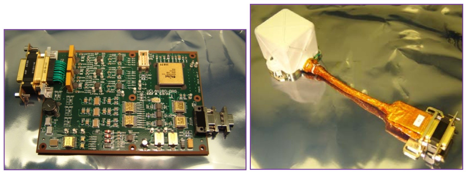
(Left) the IFG electronics and (Right) the IFG sensor inside its dust cover.
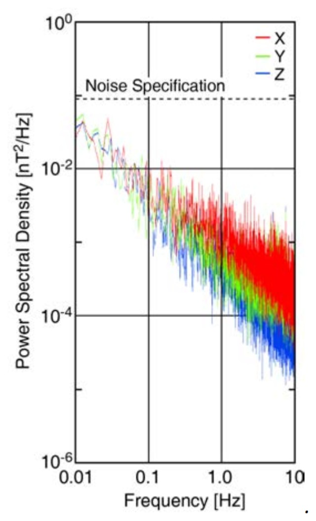
Noise in each axis as a function of frequency for the IFG instrument. X-axis noise is in red, y- axis in green, and z-axis in blue.
The IFG is designed to operate constantly throughout the mission, only being turned off in case of low power availability. The IFG sensor is sampled with the IFG electronics using a sigma-delta modulator for high-resolution analog-to-digital conversion (ADC). The sigma-delta ADC produces an 8.192 MHz, 1-bit, pulse density modulated bit stream to the Field Programmable Gate Array (FPGA). In the FPGA, the data stream goes through a Cascaded Integrator-Comb (CIC) filter, Correlation filter, and an Integrator to generate current field strength. This then goes through a block average that takes 400 samples to produce the final 24-bit, 20Hz output. This output is stored for later possible playback.
Typically during realtime transmission, on-board processing will filter and downsample this to a lower sampling rate continuous data stream, and provide a measure of energy in the magnetic field at frequencies above the continuously downlinked sampling rate. For the nominal downlink case (~38 Mbits/sol), the IFG sensor will return continuous data downsampled to 0.2Hz, and its temperature sensor will be downsampled to 0.02 Hz. Onboard processing will produce the total power in the three components of the magnetic signal above 0.1 Hz, which will be downsampled. This is expected to be indicative of high frequency magnetic variations above that resolved in the continuous pressure data, to allow identification of time intervals of magnetic events for which downlink of the full sampling rate data is desired. For magnetic events, the full 20 Hz data set from the IFG (or a downsampled version of it) can be downlinked for a short time interval (~30 minutes/sol).
Calibration
The magnetic field of the lander is unknown at the time of writing of the PIP, but will be characterized prior to launch via a series of tests that will provide information on the fields produced by time-varying power sources on the lander and the static field of the lander. It is anticipated that a major activity after deployment will be further characterization of the lander fields to enable separation of the naturally occurring Martian signals from those produced by InSight operations. Variation in gain and zero levels with temperature has been measured in the environmental chamber at UCLA and the instrument noise level and transfer function have also been measured.
see also